
What is a thyristor?
A thyristor is a high-power semiconductor device, also called a silicon-controlled rectifier. Its structure includes 4 levels of semiconductor elements, including three PN junctions corresponding towards the Anode, Cathode, and control electrode Gate. These three poles are the critical parts in the thyristor, letting it control current and perform high-frequency switching operations. Thyristors can operate under high voltage and high current conditions, and external signals can maintain their working status. Therefore, thyristors are commonly used in various electronic circuits, such as controllable rectification, AC voltage regulation, contactless electronic switches, inverters, and frequency alteration.
The graphical symbol of the Thyristor is normally represented from the text symbol “V” or “VT” (in older standards, the letters “SCR”). Additionally, derivatives of thyristors include fast thyristors, bidirectional thyristors, reverse conduction thyristors, and lightweight-controlled thyristors. The working condition in the thyristor is that when a forward voltage is used, the gate will need to have a trigger current.
Characteristics of thyristor
- Forward blocking
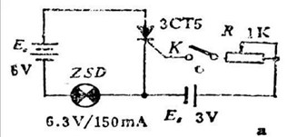
As shown in Figure a above, when an ahead voltage is used in between the anode and cathode (the anode is linked to the favorable pole in the power supply, as well as the cathode is attached to the negative pole in the power supply). But no forward voltage is used towards the control pole (i.e., K is disconnected), as well as the indicator light fails to light up. This demonstrates that the thyristor will not be conducting and contains forward blocking capability.
- Controllable conduction
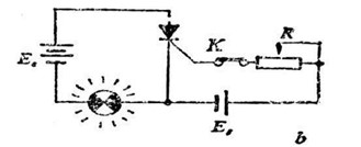
As shown in Figure b above, when K is closed, along with a forward voltage is used towards the control electrode (called a trigger, as well as the applied voltage is referred to as trigger voltage), the indicator light switches on. This means that the transistor can control conduction.
- Continuous conduction
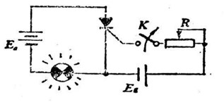
As shown in Figure c above, following the thyristor is excited, even if the voltage on the control electrode is taken off (that is, K is excited again), the indicator light still glows. This demonstrates that the thyristor can continue to conduct. At this time, to be able to stop the conductive thyristor, the power supply Ea has to be stop or reversed.
- Reverse blocking
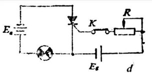
As shown in Figure d above, although a forward voltage is used towards the control electrode, a reverse voltage is used in between the anode and cathode, as well as the indicator light fails to light up at the moment. This demonstrates that the thyristor will not be conducting and can reverse blocking.
- To sum up
1) If the thyristor is exposed to a reverse anode voltage, the thyristor is at a reverse blocking state whatever voltage the gate is exposed to.
2) If the thyristor is exposed to a forward anode voltage, the thyristor is only going to conduct once the gate is exposed to a forward voltage. At this time, the thyristor is incorporated in the forward conduction state, which is the thyristor characteristic, that is, the controllable characteristic.
3) If the thyristor is excited, as long as there exists a specific forward anode voltage, the thyristor will stay excited whatever the gate voltage. That is certainly, following the thyristor is excited, the gate will lose its function. The gate only works as a trigger.
4) If the thyristor is on, as well as the primary circuit voltage (or current) decreases to close to zero, the thyristor turns off.
5) The disorder for the thyristor to conduct is that a forward voltage needs to be applied in between the anode as well as the cathode, plus an appropriate forward voltage also need to be applied in between the gate as well as the cathode. To change off a conducting thyristor, the forward voltage in between the anode and cathode has to be stop, or even the voltage has to be reversed.
Working principle of thyristor
A thyristor is basically a unique triode made from three PN junctions. It can be equivalently regarded as comprising a PNP transistor (BG2) plus an NPN transistor (BG1).
- In case a forward voltage is used in between the anode and cathode in the thyristor without applying a forward voltage towards the control electrode, although both BG1 and BG2 have forward voltage applied, the thyristor continues to be turned off because BG1 has no base current. In case a forward voltage is used towards the control electrode at the moment, BG1 is triggered to create a base current Ig. BG1 amplifies this current, along with a ß1Ig current is obtained in the collector. This current is precisely the base current of BG2. After amplification by BG2, a ß1ß2Ig current is going to be brought in the collector of BG2. This current is sent to BG1 for amplification then sent to BG2 for amplification again. Such repeated amplification forms a vital positive feedback, causing both BG1 and BG2 to enter a saturated conduction state quickly. A big current appears inside the emitters of the two transistors, that is, the anode and cathode in the thyristor (the size of the current is in fact determined by the size of the load and the size of Ea), therefore the thyristor is completely excited. This conduction process is done in a very limited time.
- After the thyristor is excited, its conductive state is going to be maintained from the positive feedback effect in the tube itself. Even when the forward voltage in the control electrode disappears, it really is still inside the conductive state. Therefore, the purpose of the control electrode is just to trigger the thyristor to change on. When the thyristor is excited, the control electrode loses its function.
- The only way to shut off the turned-on thyristor is to lessen the anode current so that it is inadequate to keep the positive feedback process. The way to lessen the anode current is to stop the forward power supply Ea or reverse the connection of Ea. The minimum anode current needed to keep the thyristor inside the conducting state is referred to as the holding current in the thyristor. Therefore, strictly speaking, as long as the anode current is under the holding current, the thyristor could be turned off.
What is the difference between a transistor along with a thyristor?
Structure
Transistors usually contain a PNP or NPN structure made from three semiconductor materials.
The thyristor consists of four PNPN structures of semiconductor materials, including anode, cathode, and control electrode.
Working conditions:
The job of the transistor relies upon electrical signals to control its closing and opening, allowing fast switching operations.
The thyristor requires a forward voltage along with a trigger current on the gate to change on or off.
Application areas
Transistors are commonly used in amplification, switches, oscillators, as well as other elements of electronic circuits.
Thyristors are mostly found in electronic circuits such as controlled rectification, AC voltage regulation, contactless electronic switches, inverters, and frequency conversions.
Way of working
The transistor controls the collector current by holding the base current to achieve current amplification.
The thyristor is excited or off by controlling the trigger voltage in the control electrode to comprehend the switching function.
Circuit parameters
The circuit parameters of thyristors are based on stability and reliability and often have higher turn-off voltage and larger on-current.
To summarize, although transistors and thyristors can be used in similar applications in some instances, due to their different structures and working principles, they have got noticeable variations in performance and use occasions.
Application scope of thyristor
- In power electronic equipment, thyristors can be used in frequency converters, motor controllers, welding machines, power supplies, etc.
- In the lighting field, thyristors can be used in dimmers and lightweight control devices.
- In induction cookers and electric water heaters, thyristors can be used to control the current flow towards the heating element.
- In electric vehicles, transistors can be used in motor controllers.
Supplier
PDDN Photoelectron Technology Co., Ltd is a wonderful thyristor supplier. It is one in the leading enterprises in the Home Accessory & Solar Power System, which can be fully involved in the progression of power industry, intelligent operation and maintenance handling of power plants, solar power panel and related solar products manufacturing.
It accepts payment via Credit Card, T/T, West Union and Paypal. PDDN will ship the goods to customers overseas through FedEx, DHL, by air, or by sea. Should you be looking for high-quality thyristor, please feel free to contact us and send an inquiry.